Bandwidth areas
This is where you create the bandwidth model. Bandwidth control determines, with the help of the bandwidth model, the optimum transmission parameters for call connection on the IP network and prevents connections from being set up if too little bandwidth is available
The available bandwidth on the IP network for a call connection can be very different as the connection may pass through different LAN areas and WAN links. Bandwidth control determines for each connection the optimum transmission parameters and monitors the number of simultaneous connections and their bandwidth requirement. If there is not enough bandwidth for another connection, said connection is not set up.
Bandwidth control depends on bandwidth model. This should actually reflect the bandwidth situation as much as possible.
Bandwidth model
In each case it calculates before a connection is set up whether or not the bandwidth available is sufficient. If not, the connection is not set up and the user obtains the congestion tone. The better the model simulates reality, the more reliably the bandwidth resources can be managed.
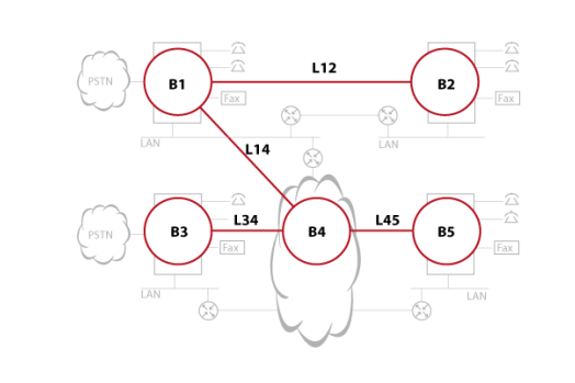
The model consists of bandwidth areas and WAN links. A bandwidth area is a network section with the same bandwidth properties. In most cases it is a LAN but the internet as a whole is also mapped as a bandwidth area.
A WAN link connects two bandwidth areas. Usually they consist of connections to an internet provider or leased lines. Frequently they have a limited bandwidth.
The WAN links are assigned to the bandwidth areas on the VoIP routing table. In the process the necessary WAN links are selected from a bandwidth area in order to set up a connection to each desired destination.
Available codecs
On a WAN link with limited bandwidth it is advisable to use a compressing codec such as G.729. It considerably reduces the bandwidth requirement and the loss of voice quality remains tolerable. In the LAN area there is usually sufficient bandwidth available and better results are achieved with the uncompressed codec. Available codecs:
-
G.711a: Uncompressed codec with high audio quality. Suitable for LAN and WAN links with large bandwidths. The bit rate is 64 kbit/s. Uses the German tone signalling process.
-
G.711u: Uncompressed codec with higher audio quality. Suitable for LAN and WAN links with large bandwidths. The bit rate is 64 kbit/s. Uses the American tone signalling process.
-
G.729: Compressed codec with medium audio quality. Suitable for WAN links with limited bandwidth. The bit rate is 8 kbit/s.
-
G.722: Uncompressed codec with very high audio quality. Condition for Hi-Q deployment of Mitel SIP phones. The bit rate is 48, 56 or 64 kbit/s.
The bandwidth control checks, before connection set up and for all partial areas of a connection (bandwidth areas and WAN links), the set codec (Preferred codec setting) and chooses the smallest of them.
DSP resources are required for real-time encoding and decoding processes in the communication server and IP terminals. G.711 required to process less DSP resources than G.729. DSP resources are provided in the form of VoIP channels.
Available frame lengths
The smaller the frame length of voice packets, the smaller the delay values generated but the greater the bandwidth requirement. For this reason we recommend that the frame length of voice packets be kept relatively small within the LAN area and relatively large for WAN connections with limited bandwidth.
The bandwidth control checks, before connection set up and for all partial areas of a connection (bandwidth areas and WAN links), the set frame length (Preferred frame length setting) and chooses the smallest of them.
You wish to keep the delay values low in case of very low bandwidth resources and, thus, choose the shortest frame length. This may prove counter-productive as the amount of frame packet is then increased, which may lead to data congestion.
Configuration
|
Parameter |
Explanation |
|
Area name |
Bandwidth area name (max. 20 characters) |
|
Preferred codec |
The ideal codec for this area. |
|
Preferred frame length |
The ideal frame length for this area. |
|
Parameter |
Explanation |
|
Name |
WAN link name (max. 20 characters) |
|
Bandwidth area A |
The first WAN link endpoint |
|
Bandwidth area B |
The second WAN link endpoint |
|
Bandwidth (kbit/s) |
Enter here the bandwidth available for VoIP on this WAN link. |
|
Bandwidth reserved for audio (kbit/s) |
Enter here the lowest bandwidth which in case of video connections must be made available for voice transmission. |
|
VoIP channels |
Displays the maximum possible number of VoIP channels that can be set up simultaneously over this WAN link |
|
RTP compression |
|
|
L2 overhead |
Enter the IP header size here. The numerical value corresponds to the header size in bytes. You can use the value based on the value table below. |
|
Preferred codec |
The ideal codec for this area. |
|
Preferred frame length |
The ideal frame length for this area. |
|
VoIP channels |
Displays the maximum possible number of VoIP channels that can be set up simultaneously over this WAN link. |
|
Protocol |
VPN (IPsec Header = 56 Byte) |
Resultant L2 overhead |
|
Ethernet (ETH) |
no |
18 |
|
yes |
74 |
|
|
PPP / PPPoA / FrameRelay |
no |
6 |
|
yes |
62 |
|
|
PPPoE |
no |
26 |
|
yes |
82 |
|
Parameter |
Explanation |
|
Own bandwidth area |
Bandwidth area from which the connections are set up. |
|
Destination bandwidth area |
Nearest bandwidth area on the control path to the connection destination. |
|
WAN link |
|
|
VPN peer bandwidth area |
You need to identify links with VPN by entering the VPN end (VPN peer). The bandwidth model then automatically takes the 56 byte larger L2 overhead into account when calculating the bandwidth requirements. |
|
Parameter |
Explanation |
|
Node |
Node number in an AIN. The master has number 0. |
|
Card/module |
Card slot on which the module is fitted (no entry for the standard media switch). |
|
Slot on card |
Module slot on the card (no entry for the standard media switch). |
|
Module |
Short description of the module (no entry for the standard media switch). |
|
State |
When the card is in operation, In service is displayed here. |
|
IP address |
Module IP address (the standard switch has the same IP address as the nodes) |
|
Bandwidth area |
Bandwidth area in which the node is located. |
First steps.: Determining the bandwidth topology
In the following you map out the bandwidth areas and the WAN links.
-
Draw up a diagram of the bandwidth topology. To do so map out one bandwidth area for each IP section with its own LAN.
-
Map out another bandwidth area to represent the internet.
-
Map out the WAN links that connect the individual bandwidth areas.
-
For all the WAN links determine the bandwidth available for voice traffic. To do so measure the level of data traffic on the WAN link and subtract that value from the available bandwidth.
The model’s accuracy depends on this calculation.
Second step: Set up bandwidth areas
The instructions below explain the procedure for configuring the bandwidth areas:
-
First create the bandwidth area in which the communication server or Master is located. The easiest way to do this is to use the standard bandwidth area. Besides the name enter the values for the preferred frame length and codec. The bandwidth control uses these values to find the optimum setting for a call connection. As we are dealing with a LAN, a good choice is G.711 and a frame length of 20 ms.
-
Open the remaining bandwidth areas.
Third step: Set up WAN links
The instructions below explain the procedure for configuring the WAN links:
-
First open one or more WAN links to the bandwidth area of the communication server/Master. Enter as available bandwidth the values fixed in the bandwidth topology.
-
Define the WAN link parameters. Fix the codec and frame length based on the available bandwidth.
-
Open and configure the remaining WAN links.
Fourth step: Configure VoIP table
When the WAN links are created, the VoIP routing table is filled out automatically as much as possible. Configure the entries in accordance with the information given in AIN.
-
Define all the routing paths starting from the first bandwidth area and enter them. If routing paths pass through the same WAN links to destinations in various bandwidth areas, select for the destination bandwidth area the option Undetermined.
-
Repeat this procedure for each bandwidth area.
|
Own bandwidth area |
Destination bandwidth area |
WAN link |
|
B1 |
Undetermined |
L12 |
|
B2 |
Undetermined |
L12 |
|
B4 |
Undetermined |
L14 |
|
B3 |
Undetermined |
L34 |
|
B5 |
Undetermined |
L45 |
|
Own bandwidth area |
Destination bandwidth area |
WAN link |
|
B1 |
Undetermined |
L14 |
|
B2 |
Undetermined |
L12 |
|
B4 |
Undetermined |
L14 |
|
B3 |
Undetermined |
L34 |
|
B5 |
Undetermined |
L45 |
|
B1 |
B2 |
L12 |
|
B4 |
B3 |
L34 |
|
B4 |
B5 |
L45 |
See also...